Modern pressure vessel software tools have transformed engineering practice. They automate complex calculations, check compliance with international codes, and can generate both two-dimensional drawings and three-dimensional models. Among their most promoted features is drawing regeneration: the automatic production of vessel sketches, general arrangements, and bill of materials directly from the design process.
These tools usually export 2D outputs in formats such as DXF or DWG, and 3D outputs in neutral formats like STEP or IGES. On the surface, this appears to provide a seamless bridge between design offices and manufacturing shops. In theory, a manufacturer could import these outputs directly into a CAD or CAM system and proceed to fabrication.
In reality, the regenerated drawings are far less useful to fabricators than they are to licensors or designers.
Why Software Output Falls Short for Manufacturing
The majority of automatically generated drawings serve well as communication tools – they illustrate vessel geometry, nozzle orientation, and overall dimensions. However, they fall short as fabrication documents. Several issues explain this gap:
v Absence of manufacturing detail
Essential shop information such as weld bevels, edge preparations, tolerances, forming allowances, and post-weld heat treatment requirements is rarely included. Without these details, a drawing cannot guide actual construction.
v Simplified representation of geometry
The models assume perfectly formed shells, heads, and welds. Real fabrication involves bending tolerances, rolling offsets, and welding shrinkage—none of which are captured by idealized software output.
v Dimensional ambiguity
Automatically generated drawings tend to include only nominal dimensions. Manufacturing requires full tolerance, datums, and geometric dimensioning, which are left for the fabricator to establish.
v Mismatch of intent
The purpose of these tools is to ensure compliance with design codes and communicate licensor intent. They are not intended to encode the diverse practices of fabrication shops, which vary in welding procedures, material sourcing, and quality standards.
Because of these limitations, manufacturers rarely rely on regenerated drawings as shop documents. Instead, they rebuild or adapt the models within their own CAD systems to add the missing detail.
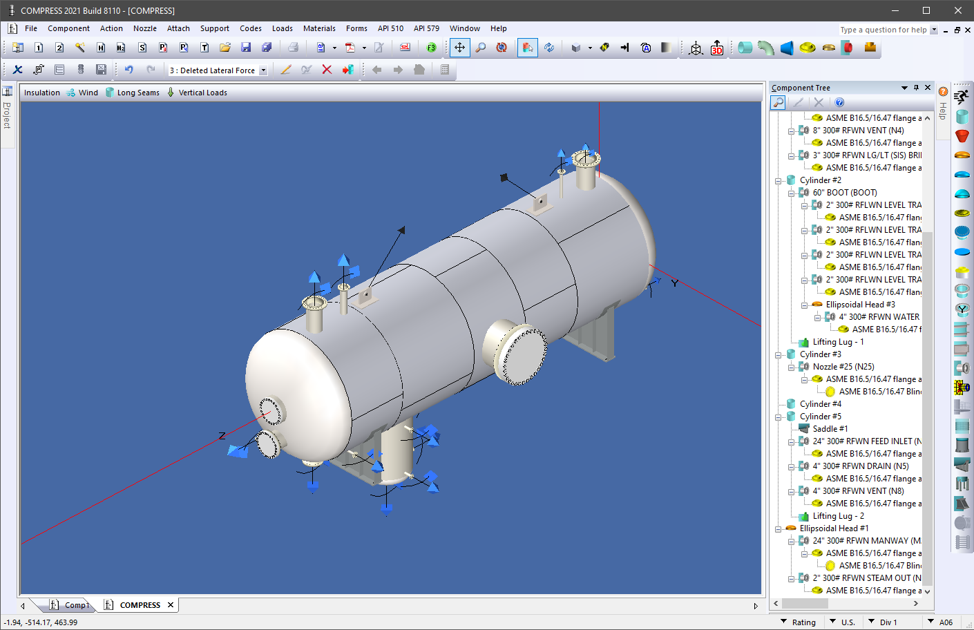
The Role of STEP Files
Among the available formats, the STEP file stands out as the most useful to industry. It preserves solid geometry in a neutral, widely supported form. Fabricators often use STEP models to:
v Get a 3D model as calculated in order to visualize the construction faster
v Calculate weights and centers of gravity.
Despite these advantages, STEP files are still only part of the solution. They lack embedded tolerances, weld definitions, and material annotations. The geometry is accurate but “silent” about how the vessel should actually be built.
Why Better Drawings Are Hard to Automate
The limited usefulness of regenerated drawings is not simply a matter of underdeveloped software. It reflects the inherent complexity of vessel fabrication:
v Shop variability: Each fabricator follows unique welding procedures, tolerances, and assembly methods.
v Material behavior: Rolling, forming, and post-weld treatment affect geometry in ways that cannot be universally predicted.
v Standards mismatch: Design codes regulate safety and strength, not the fine details of how to cut or weld a plate.
v Loss of design intent: Exported models are often “dumb solids” with no parametric history, making it difficult to adapt them to specific shop practices.
Given this variability, no generic software can produce drawings that are universally fabrication-ready.
Alternative Approaches
While current outputs have limitations, several alternative methods are emerging:
v CAD augmentation: Import neutral files into a CAD system, then add weld symbols, tolerances, and shop-specific notes
v Template libraries: Apply standardized shop details—such as common supports, heads, or flanges—onto simplified vessel models.
v AI-driven drawing generation: A promising future direction is to use AI to read the design report itself, extracting dimensions and code-derived data to automatically generate 2D fabrication drawings. This approach could reduce the manual re-detailing now required.
Conclusion
Pressure vessel analysis tools have advanced design efficiency and code compliance, but drawing regeneration remains more useful for communication than fabrication. STEP models provide valuable geometry, yet manufacturers still need to enrich them with tolerances, weld details, and process notes.
The core challenge lies in the diversity of manufacturing practices and the difficulty of encoding shop knowledge in generic tools. Until alternative methods – such as AI assisted drawing generation – become reliable, regenerated drawings will remain sketches of intent rather than fabrication deliverables.